You will need:
- A small Phillips (cross-head) screwdriver - preferably a few millimeters will do.
- A soldering iron,
- Solder,
- Either the 'ST-4 Conversion Kit' which can be purchased from Opticstar (in the U.K.) or Shoestring Astronomy (in the U.S.). Alternatively, you can by any 6 core wire with an RJ12 connector - more on that shortly.
- An EQ4 / 5 Dual Axis motor control handset.
- Either an ASCOM compatible guide camera with ST-4 port or any other suitable guidecam / webcam and a GPUSB* guideport interface, also available from the above suppliers.
- Autoguiding software. I use PHD, which is free, but there are others available.
- About an hour of spare time.
First, I will introduce the components we will be using:
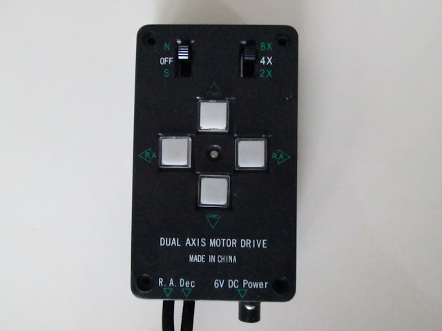 |
| EQ4/5 Dual Axis Handset |
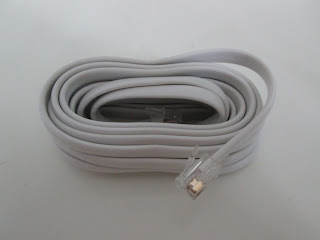 |
| ST-4 Cable - RJ12 in non-astronomical circles. |
These two images show the wiring layout of the cables used in this example. Be sure to check that your cables either use the same configuration (White - Brown - Red - Green - Yellow - Blue from left to right with the release clip of the connector facing towards you), or that you can familiarise yourself with the configuration of your cable in order to match the correct cables to the correct soldering joints. Incorrect wiring could lead to damage of your equipment.
Whilst we're on the subject I must point out that this modification is in no way recommended by myself or any of the suppliers of manufacturers involved - you undertake this at your own risk, and any warranties will be invalid.
Right, with the warnings done and tossed hastily to the side, provided you have all you need, it's time to begin!
STEP 1: Remove the buttons
Gently prise off the four buttons with a screwdriver. Use 2 screwdrivers if possible to avoid breaking the buttons. Lay the buttons to on side.
Step 2: Removing the top cover:
Then, the handset cover should come cleanly off and you should be left with the following:
Don't be afraid of what you see if you're unfamiliar with electronics - you can ignore 99% of everything that's in here. Just be careful not to touch anything you don't have to - particularly the chip on the lower board (which you'll see in a moment).
Step 3: Open up some access.
Loosen and remove the two screws that fix the top board to the bottom board.
The top board now lifts away revealing the bottom board, which is the part that the hand controller uses to communicate with the mount. Note the large chip which I mentioned earlier. Be careful to have as little contact with this board as possible.
There are three small screws holding the bottom board in place - remove these also.
Step 4: The Cable grip.
This is the cable grip - we will need to remove this in order to lay our new cable underneath it later on.It is most convenient to un-do this grip now, so as not to hamper yourself later on.
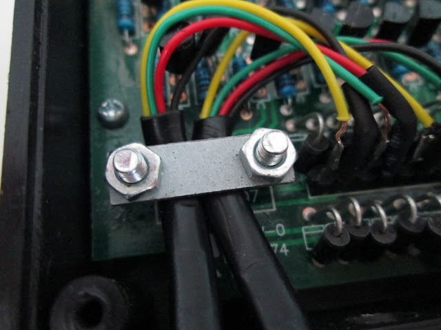 |
| The cable grip. Note the small screw in the background - this should be removed, along with 2 others, as part of step 3. |
Ensure that the power socket is dislodged from it.s nook, being careful of the delicate wires that connect it to the main board. These are fragile and can break if tugged on.
Gently pull the main board away from its housing and turn over. You will see two bolts which hold the cable grip in place. Remove them.
You should now be left with the following items:
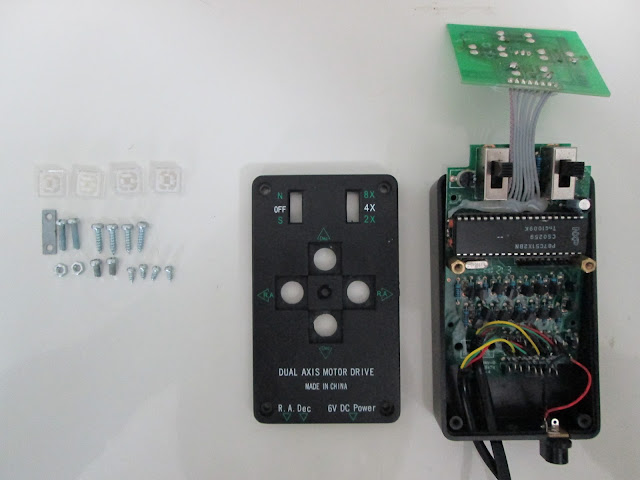 |
| Note: You should have one more of the smallest screws than this - I have reattached the power socket for ease of photographing! |
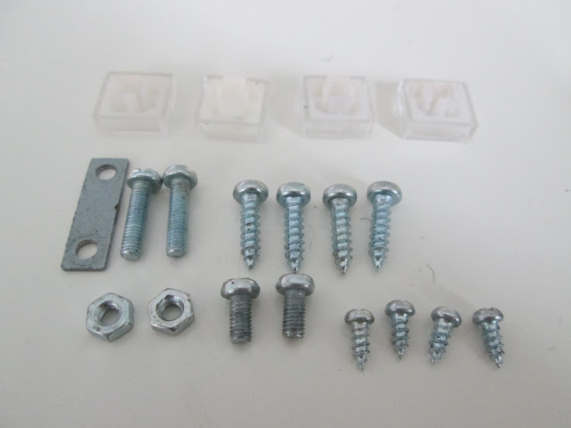 |
| Again, there should be 5 of the smallest screws. |
You can either chose to drill a hole:
Step 6: Time to solder!
First, cut back the white (Pin 1) wire. This is unused by the handset. It is important not to have this hanging loose within the handset, as it may cause short circuiting or unpredictable behaviour.
Solder the wires into the follwing configurations. If you are a better solderer than me, which is very likely, your end result may look a tad tidier than this!
Now that you have your wires soldered in place, it's importand to test the operation of the unit. Carefully plug the unit in. Be EXTREMELY careful not to touch any exposed wires or contacts at this point. There is a risk of electric shock. Carefully press each button, and ensure that this causes the green L.E.D. to turn red. If you have a stepper motor from your mount to hand, you can always plug this in to ensure that the buttons are doing what they're supposed to. Personally, I check the functionality of the unit after every step from here on. It's easy to break off a solder joint or get a short circuit, so a quick check is a good idea.
Step 7: Put 'er back together!
First, put the three ST-4 cables beneath the cable grip and fasten it firmly. This is important as a loose grip will lead to broken solder joints in the future. A firm hold keeps everything together!
Slot the main board back into place and attach with three of the small screws. Use one more of these to reattach the lower side of the power socket.
Reattach the upper board with the two short, fat screws as follows:
And then replace the outer cover using the four long screws to hold it into place.
Use the remaining small screw to firmly attach the power socket, clip-press the buttons back into place, and you've completed your ST-4 Guideport modification!
The following describes the connections for the two options of using your guidescope and camera:
Using GPUSB Guideport Interface:
Camera<----(USB Cable)-----PC
PC----(Built in USB Cable)----->GPUSB-----(ST-4 Cable)----> Handset
Using ASCOM compatible camera with ST-4 port:
PC---(USB Cable)---->Camera----(ST-4 Cable)---->Handset
PLEASE NOTE: The EQ5 is not the ideal mount for astrophotography, and it will only enable a low payload capacity to be used. I would suggest considering the use of a so-called 'finder-guider' rather than a dedicated guidescope, as these keep the weight to a minimum. If you do wish to use larger scopes with larger guiders, filter wheels and other equipment, you should consider upgrading to a sturdier mount. Of the more affordable mounts, consensus often favours the EQ6 and NEQ6 mounts, which have served many successful amatuer astrophotographers well. The HEQ5 should really be seen as the minimum, and those taking on the EQ5 are either just slightly mad, or enjoy a challenge. Having said that, many people have made excellent use of this great mount. It remains to be seen if I manage to do so also!
Please also note that I accept no responsibility for any damage to your equipment during this process. I personally am notorious for breaking things and being a general bodge-artist (yes, that was the polite version), so my instructions should not be followed by anybody at any time!




No comments:
Post a Comment
Please refrain from using strong or offensive language on this page - its entirely feasible my Mum might read this, and I dont want you giving her any new words she doesnt know already ;)
Seriously though, please remain respectful to others and of other peoples opinions. Happy posting!